This is an older post, originally published on my previous tinkering blog at electronza.com. While it dates back a few years, it remains just as relevant today.
At the time, I was working on an IoT node based on the ESP8266, designed to collect sensor data and upload it to cloud services.
One of the main challenges was running the node on battery power. It had to operate for extended periods with no human intervention. I had found a 9800 mAh LiPo battery that should have provided enough energy to keep it running for several months. Still, achieving that required minimizing the ESP8266’s power consumption and protecting the LiPo battery from over-discharge (typically below ~3 V).
On its own, this proved to be a challenging problem — one that deserved a dedicated blog post. So, this article is focused on two aspects: reducing the power consumption of ESP8266 modules and protecting LiPo batteries from over-discharging.
ESP8266 Low Power Modes
The first and simplest way to cut down a few milliamps was to remove the power LED.
Some ESP8266 boards had a trace that could be cut, such as the ESP8266 Thing Dev I used in the project. On other boards, the LED had to be physically removed – SMD hot tweezers were a must. Either way, this step reduced consumption by about 8–10 mA.
Next, I looked into the ESP8266 sleep modes. There were three sleep modes, summarized below:
| Modem sleep | Light sleep | Deep sleep | |
| WiFi | OFF | OFF | OFF |
| System clock | ON | OFF | OFF |
| RTC | ON | ON | ON |
| CPU | ON | Pending | OFF |
| Substrate current | 15mA | 0.4mA | ~ 20µA |
| Avg. Current DTIM = 1 | 16.2mA | 1.8 mA | – |
| Avg. Current DTIM = 3 | 15.4 mA | 0.9 mA | – |
| Avg. Current DTIM = 10 | 15.2 mA | 0.55 mA | – |
* On some routers, you cannot change the DTIM value
ESP8266 Deep Sleep
The most interesting mode for a sensor node that periodically woke up and sent data was deep sleep.
In the Arduino IDE, the ESP8266 could be put into deep sleep using:
ESP.deepSleep(sleepTimeSeconds * 1000000);As shown in the example below:
#include <ESP8266WiFi.h>

/* ESP8266 Deep-sleep mode */
void setup() {
  Serial.begin(115200);
  Serial.setTimeout(2000);

  while(!Serial) { }

  Serial.println("I'm awake.");
  Serial.println("Going into deep sleep for 20 seconds");

  ESP.deepSleep(20e6); // 20 seconds
}

void loop() {}
However, there was a catch: to wake up the ESP8266, the RST pin had to be connected to GPIO16 (WAKE).
- On the ESP8266 Thing Dev, this was done by closing the SJ2 jumper
- On other boards, a wire connection between RST and GPIO16 was required
Another aspect is that the ESP8266 will lose everything in its memory, and it will run the code just as it does when it’s powered on for the first time.
Of course, one can save some context variables in the EEPROM. But if a node wakes up every five minutes, this will result in having 288 writes to the EEPROM per day. The AT25SF041 used by ESP8266 Thing Dev is rated for 100,000 Program/Erase Cycles. That means that the EEPROM will wear out in less than one year.
ESP8266 – Turning Off the Modem
This is a neat trick I found in the Arduino examples, in the ESP8266 board version 2.5.0 (or higher). It allows the ESP8266 to start with the modem off, then start the modem at the desired moment in the code. When dealing with slow sensors, such as the DGS-H2S from SPEC Sensors, one can use this trick to keep the modem off while the sensor data is collected and turn it on just before uploading to online services.
#include <ESP8266WiFi.h>

#ifndef STASSID
#define STASSID "your-ssid"
#define STAPSK  "your-password"
#endif

void preinit() {
  ESP8266WiFiClass::preinitWiFiOff();
}

void setup() {
  Serial.begin(115200);
  Serial.setDebugOutput(true);

  Serial.println("sleeping 5s");
  delay(5000);

  Serial.println("waking WiFi up, sleeping 5s");
  WiFi.forceSleepWake();

  delay(5000);
  Serial.println("connecting to AP " STASSID);

  WiFi.mode(WIFI_STA);
  WiFi.begin(STASSID, STAPSK);
}

void loop() {}
During testing, a simple ammeter showed that consumption stayed around ~20 mA with WiFi off and increased to ~75–80 mA when WiFi was active.
Protecting the battery
This is where things become interesting. By design, most ESP8266 boards do not allow direct measurement of the battery voltage (Vin) without external components. However, there was a workaround: one can detect a discharged battery indirectly, by measuring the input voltage of ESP8266 – that would be V3.3.
This was enabled by adding:
ADC_MODE(ADC_VCC);and reading the value with:
uint32_t voltage = ESP.getVcc();as shown in the example below:
// Load Wi-Fi library
#include <ESP8266WiFi.h>

// Replace with your network credentials
const char* ssid     = "myssid";
const char* password = "mypassword";

ADC_MODE(ADC_VCC);
uint32_t Batt;

// Set web server port number to 80
WiFiServer server(80);

// Variable to store the HTTP request
String header;

void setup() {
  Serial.begin(9600);
  while(!Serial);

  // Connect to Wi-Fi network with SSID and password
  Serial.print("Connecting to ");
  Serial.println(ssid);
  WiFi.begin(ssid, password);
  while (WiFi.status() != WL_CONNECTED) {
    delay(500);
    Serial.print(".");
  }
  // Print local IP address and start web server
  Serial.println("");
  Serial.println("WiFi connected.");
  Serial.println("IP address: ");
  Serial.println(WiFi.localIP());
  server.begin();
}

void loop(){
  WiFiClient client = server.available();   // Listen for incoming clients

  if (client) {
    Serial.println("new client");
    // an http request ends with a blank line
    boolean currentLineIsBlank = true;
    while (client.connected()) {
      if (client.available()) {
        char c = client.read();
        Serial.write(c);
        // if you've gotten to the end of the line (received a newline
        // character) and the line is blank, the http request has ended,
        // so you can send a reply
        if (c == '\n' && currentLineIsBlank) {
          // send a standard http response header
          client.println("HTTP/1.1 200 OK");
          client.println("Content-Type: text/html");
          client.println("Connection: close");  // the connection will be closed after completion of the response
          client.println("Refresh: 5");  // refresh the page automatically every 5 sec
          client.println();
          client.println("<!DOCTYPE HTML>");
          client.println("<html>");

          // output the battery value
          Batt = ESP.getVcc();
          client.println("Battery voltage is: ");  // refresh the page automatically every 5 sec
          client.println(Batt);

          client.println("</html>");
          break;
        }
        if (c == '\n') {
          // you're starting a new line
          currentLineIsBlank = true;
        } else if (c != '\r') {
          // you've gotten a character on the current line
          currentLineIsBlank = false;
        }
      }
    }
    // give the web browser time to receive the data
    delay(1);
    // close the connection:
    client.stop();
    Serial.println("client disconnected");
  }

}
the ESP8266 is configured to read the V3.3 voltage by placing ADC_MODE(ADC_VCC); on top of the sketch. Then, the battery voltage in mV is read as in uint32_t getVcc = ESP.getVcc();
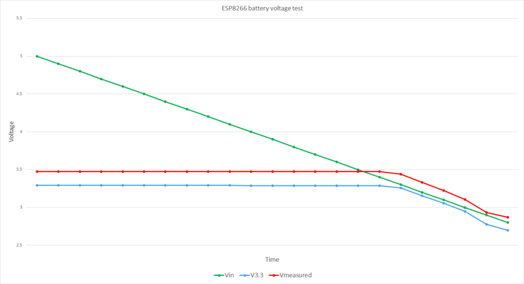
In my experiments, I found the following relationship among Vin, V3.3, and the voltage measured by the ESP.getVcc(); This applies to the ESP8266 Thing Dev, which uses AP2112K-3.3V LDO regulator. Some other boards might behave differently, so you will have to redo my experiment.
| Vin | V3.3 | Vmeasured/1000 |
| 5 | 3.2904 | 3.475 |
| 4.9 | 3.2905 | 3.475 |
| 4.8 | 3.2905 | 3.475 |
| 4.7 | 3.2904 | 3.474 |
| 4.6 | 3.2905 | 3.475 |
| 4.5 | 3.2904 | 3.474 |
| 4.4 | 3.2905 | 3.475 |
| 4.3 | 3.2905 | 3.475 |
| 4.2 | 3.2906 | 3.475 |
| 4.1 | 3.2905 | 3.475 |
| 4 | 3.29 | 3.474 |
| 3.9 | 3.2899 | 3.474 |
| 3.8 | 3.2899 | 3.474 |
| 3.7 | 3.2898 | 3.474 |
| 3.6 | 3.2897 | 3.473 |
| 3.5 | 3.2897 | 3.473 |
| 3.4 | 3.2895 | 3.472 |
| 3.3 | 3.2575 | 3.44 |
| 3.2 | 3.153 | 3.331 |
| 3.1 | 3.0555 | 3.226 |
| 3 | 2.947 | 3.106 |
| 2.9 | 2.775 | 2.936 |
| 2.8 | 2.7 | 2.87 |
In my experiments (performed on the ESP8266 Thing Dev, which used an AP2112K-3.3V LDO regulator), I observed the following:
- There was an offset of about 0.18 V between the measured value and the actual V3.3
- The voltage remained stable while Vin was above 3.3 V (regulated region)
- Once Vin dropped below 3.3 V, the regulator output began to drop
Most importantly:
- When the battery voltage reached ~3.0 V (a safe discharge limit for LiPo batteries), the value returned by
ESP.getVcc()was about 3100 mV
This provided a practical threshold for detecting low-battery conditions.
// Low voltage detection
// Note that we read Vin, and not the battery voltage,
// as the battery voltage is not accessible to be measured
// ESP8266 thing uses AP2112K-3.3V
// https://www.diodes.com/assets/Datasheets/AP2112.pdf
// Low DropoutVoltage (3.3V): 250mV (Typ.) @IOUT=600mA+

#include <ESP8266WiFi.h>

ADC_MODE(ADC_VCC);
int Batt;

// do other things here

void setup() {

  // ********************************************************************************
  // Check battery status
  // ********************************************************************************
  // Reads Vin (not battery voltage!!!)
  // But Vin = battery voltage if battery_voltage < 3.3V
  Batt = ESP.getVcc();
  // If the battery is discharged don't go any further!!!
  if(Batt < 3100){
     // Deep sleep for as long as you can
     ESP.deepSleep(ESP.deepSleepMax());
  }
  // your code goes here
}

void loop() {
  // your code goes here
}
In this approach:
- The voltage was checked immediately after boot
- If the value was below the threshold, the ESP8266 entered deep sleep for the maximum possible duration
- It periodically woke up, checked again, and returned to sleep if needed
It is worth noting that other components (such as sensors) still consumed power, but the overall discharge rate was significantly reduced.